
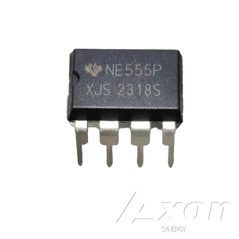
NE555 Precision Timer IC - DIP-8 Oscillator for Electronics Projects
The 555 timer is the most produced integrated circuit in history, and the NE555 in DIP-8 package remains the standard component for timing, oscillation, and pulse generation after more than 50 years of production. If you are learning electronics, building a 555 flasher or tone circuit is still one of the best foundational exercises available - it teaches RC timing, duty cycle, and output driving in a single compact package.
In astable mode, the NE555 oscillates continuously at a frequency set by two resistors and a capacitor - useful for LED flashers, tone generators, PWM motor speed control, and clock signals for logic circuits. Frequency ranges from under 1Hz (slow blink) to 100kHz (well into audio range). In monostable mode, one input pulse triggers a single output pulse of precise, adjustable duration - used for switch debouncing, time delays, and one-shot alarm pulses.
The NE555P drives up to 200mA directly from the output pin, enough to drive a small buzzer, LED array, or relay coil without a buffer transistor. The 4.5-16V operating range is compatible with 5V Arduino circuits and 9V or 12V external power supplies. The 8-pin DIP package plugs directly into any solderless breadboard and transfers cleanly to through-hole PCBs for permanent builds. Our Gas Leak Alarm and Parking Sensor project kits both use this IC as the alarm driver.
Specifications
| Part Number | NE555P |
|---|---|
| Package | 8-Pin DIP |
| Operating Voltage | 4.5V-16V |
| Output Current | Up to 200mA |
| Frequency Range | DC to 100kHz |
| Modes | Astable & Monostable |
Frequently Asked Questions
What is the difference between astable and monostable mode?
In astable mode, the 555 oscillates continuously, producing a square wave output at a frequency set by two resistors and a capacitor. It is useful for blinking LEDs, generating tones, and PWM signals. In monostable mode, the 555 produces a single output pulse of fixed duration when triggered, then returns to idle. It is useful for time delays, switch debouncing, and one-shot alarms.
How do I calculate the frequency for an astable 555 circuit?
In astable mode, frequency is approximately 1.44 divided by ((R1 + 2 times R2) times C), where R1 and R2 are in ohms and C is in farads. For a 1Hz blink with R1=1k ohm, R2=68k ohm, and C=10uF: 1.44 divided by (137,000 times 0.00001) equals approximately 1.05Hz. Search '555 timer calculator astable' for online tools that output component values for any target frequency.
Can I use the NE555 with a 3.3V ESP32 or Arduino?
The NE555 requires a minimum supply of 4.5V, so it cannot run from a 3.3V supply. Power the 555 separately from 5V or higher. If you need the 555 output to feed a 3.3V GPIO pin, use a voltage divider on the output. For true 3.3V or lower operation, look at the CMOS variants - the TLC555 or LMC555 operate down to 2V or lower.
Can the NE555 drive a buzzer or relay directly?
Yes. With up to 200mA output current, the NE555 can directly drive a small piezo buzzer, an LED array, or a relay coil. For inductive loads like relays or small motors, add a flyback diode such as a 1N4148 or 1N4007 in parallel with the load to prevent voltage spikes from damaging the IC. For loads above 200mA, buffer with a transistor such as a 2N2222 or TIP31.
How many NE555 ICs come in this listing?
Each listing is for one (1) NE555P timer IC at $0.99. With 80 in stock, you can easily order several for multiple projects. Just increase the quantity before adding to cart.